
SMPS (Switched Mode Power Supply) design is becoming less common in electronics design with integrated magnetics module solutions becoming ever better and smaller. Those that do make their own SMPS designs have to consider cost, space and EMC. In this short series of articles, we want to give you some guidelines on several aspects of buck, boost and buck/boost SMPS designs so that you will be able to choose, design and integrate one into your designs without problems.
Part 2: Dimensioning the Main Components
Missed part 1? No problem, here’s the link.
Input filter
The input filter will stop SMPS switching noise from propagating out of the SMPS and provides a low impedance buffer for the SMPS to run off. Usually, one can find an element of inductance and capacitance in the input filter. When designing such a filter, make sure that the impedance that is seen by the SMPS on its input is sufficiently low from DC to at least 5 times the switching frequency. It is worth the effort to simulate the input filter to ensure this.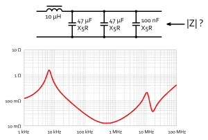
Be careful when using series inductors, as they resonate with the input capacitor(s). This causes a peak in the filter impedance at frequencies around the feedback loop cut-off frequency, which may cause instability of the regulator.
Ferrite beads are practical but may have a considerable amount of inductance and resistance on relatively low frequencies.
Adding a small (RF) capacitor to the input filter can facilitate high-frequency routing on the PCB layout. We’ll talk about that later.
>h3>Output inductor
Make sure that the sum of DC current and ripple current never exceeds the inductor’s fully derated saturation current. The inductor should also satisfy the requirements for DC current. Also check that the inductor’s SRF (Self-Resonant Frequency) is adequately above the switching frequency of your SMPS.
Generally speaking, a higher inductance will produce less ripple current and promote continuous conduction, which are good traits for efficiency and EMC performance. Higher inductance does generally mean bigger size, higher cost and/or higher inductor ESR. For designs that require high efficiency, try to find a good trade-off between inductor value and ESR.
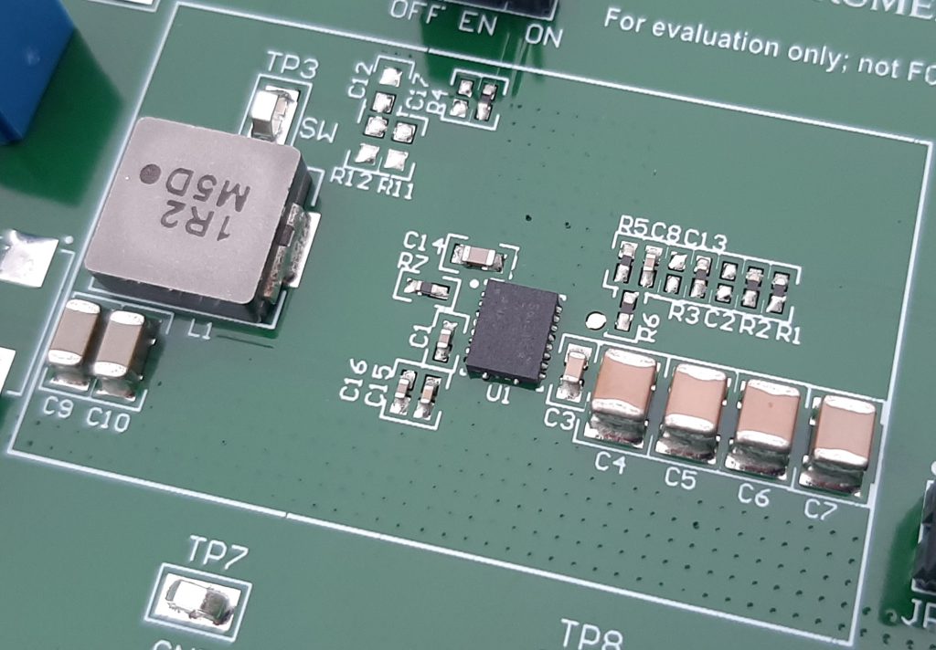
Using shielded or at least semi-shielded inductors is a good practice to stay out of EMC-related trouble. Remember that inductor shielding is imperfect and even shielded inductors have a stray magnetic field. The closest victim to this field usually is the PCB.
Output Capacitor
Carefully inspect the datasheet of the SMPS regulator for output capacitor requirements. Most regulators require a minimum output capacitance for stable operation, some also require a minimum amount of output capacitor ESR. Ceramic multilayer capacitors suffer from the DC bias effect that reduces the effective capacitance with increasing DC bias. Take this derating and the general tolerance into account when calculating the minimum required output capacitance.
Also look for maximum capacitive load requirements. Because this requirement has to do with loop stability, all capacitors on the PCB that are connected to the output must be included in the maximum capacitive load calculation, not just the ones close to the regulator. A ferrite bead usually does not isolate large capacitors from the power supply rail.
Make sure that the output capacitor has sufficiently low impedance from 1/20th of the switching frequency of the regulator up to 5 times the highest load switching frequency. This low impedance is to be provided locally to the regulator, as all other capacitors on the PCB connected to the output don’t contribute to the high frequency decoupling.
It is worth the effort to simulate the output capacitance to ensure this. Also take into account the inductance of the traces to the capacitors, as this significantly influences the impedance of the output capacitor over frequency.
General Guidelines
- Do the math. With so many free calculation and simulation tools available there is no excuse to not at least simulate the filters. (My personal favourites are an old version of Micro-Cap, the Saturn PCB Toolkit and Excel.) Incorporating ESL, ESR, capacitance derating and trace inductance can give you surprising results and insights.
- Generally speaking, a higher value switching inductor means less ripple current and by effect lower ripple voltage on the SMPS output as does higher output capacitance